Introduction
The complexity of the modern anesthesia machine, with its numerous components and accessory attachments, is such that multiple factors can lead to a loss of pressure within the breathing circuit and result in inadequate ventilation of the patient’s lungs. It is the objective of this article to review how these multiple causative factors can produce a breathing system low-pressure alarm condition during automatic mechanical ventilation, and what measures the anesthesiologist should perform to efficiently and systematically correct the underlying problem.
The Low-Pressure Alarm
In 1986, the ASA1 adopted as a basic monitoring standard the continuous use of a device capable of detecting a disconnection of breathing system components. The implementation of such a standard followed the Harvard Medical School studies conducted by Eichhorn2,3 et al. which supported the contention that enhanced intraoperative monitoring, inclusive of a disconnection monitor, could significantly prevent patient injury.
A low-pressure monitoring device is designed to annunciate an alarm if the breathing system pressure fails to exceed a minimum threshold pressure within a fixed time. The low-pressure alarm is important because it can alert the anesthesiologist to major problems such as disconnections, leaks, accidental tracheal extubations, failures in the fresh gas flow system, ventilator setting errors, internal anesthesia machine obstructions, and scavenging system problems, to be discussed in further detail below.
A low-pressure alarm is not intended to be a specific disconnection alarm; however, when used in conjunction with other monitors/alarms, it may be of help in warning of disconnections. Absence of a capnogram, as well as a zero level reading on the spirometer or pressure trace, can also be indications of a disconnect. In general, the use of multiple monitors enhances the level of vigilance and diagnostic utility.
There are several types of low pressure monitors in current use. For example, the DPM-S pressure monitor4 (North American Dräger, Inc., Telford, PA), which is located upstream of the inspiratory unidirectional valve in a circle breathing system, will annunciate an alarm (the low-pressure alarm) when the maximum pressure in the breathing system is less than the pressure threshold set on the minimum ventilation pressure switch for more than 15 seconds. The recent Ohmeda5 anesthesia machines (7800 and 7900 series ventilators) have the low-pressure sensing port immediately downstream of the unidirectional inspiratory valve. Older anesthesia machines may have freestanding, add-on low-pressure monitors that may not be automatically enabled. In the latter case, the anesthesiologist needs to remember to enable and set the circuit low-pressure alarm.
Because the low-pressure alarm is annunciated much more frequently than the three other pressure alarms (high, subatmospheric, and continuous), the low-pressure alarm is arguably the most important breathing circuit pressure monitor6; however, the high-pressure alarm is important in the detection of hazardous situations that can lead to pulmonary barotrauma.
Location of Pressure Sensing Port in the Breathing System
The location from which pressure in the breathing system is sensed will affect diagnostic utility.7 Ideally, the pressure should be sensed near the Y-piece connected to the tracheal tube in the immediate vicinity of the patient’s airway. In practice, however, problems can arise with the Y-piece location owing to buildup of condensation and risks of contamination from nearby secretions. Consequently, manufacturers of anesthesia machines have moved the site of the pressure sensor to other locations within the breathing system.
False Negatives
A false-negative condition arises when a true low-pressure condition exists in the breathing circuit, but the pressure monitor does not annunciate an alarm because its threshold criteria for a minimum pressure are satisfied at the pressure sensing location. The most common cause of a false negative may be the failure of the anesthesiologist to appropriately set the minimum pressure threshold. If the monitor’s minimum pressure threshold is set to a low pressure, the monitor’s threshold may be satisfied in the case of a partial disconnect and an alarm will not be annunciated. This can happen,8,9 for example, when there is a partial obstruction of the breathing circuit at the point of disconnection, such that the decreased pressure resulting at the sensing location still exceeds the alarm minimum pressure threshold. For this reason, it has been recommended6 that the low-pressure threshold, if adjustable, should be set only slightly below the maximum inspiratory pressure.
Other reported causes of false-negative conditions include:
(a) an occlusion, which is located downstream of the pressure sensing port, will cause a low-pressure state distal to the occlusion and a high-pressure state at the pressure sensing port proximal to the occlusion. Thus the distal low pressure may not be [immediately] detected.
(b) a patient’s pillow partially occluded the disconnected Y-piece, thereby preventing the detection of the underlying disconnection.8
(c) in North American Dräger Narkomed 2 and 2A anesthesia machines with AV-E ventilators, very high inspiratory flow rates can cause a compression distortion of the bellows during the inspiratory phase of the cycle. The generated pressure pulse is transmitted to the breathing circuit and produces a small gas flow. The transient pressure pulse exceeds the low-pressure threshold such that, even in the presence of a total disconnect, the disconnect alarm is not triggered.10 This problem is not unique to Narkomed models, but also occurs with other anesthesia breathing systems.11
(d) the back pressure generated by a cascade humidifier, or by a water-logged Portex Humid-Vent 1 humidifier12 or a heat and moisture exchanger (HME)13, may functionally disable the ventilator disconnect alarm.
(e) if a descending bellows (which exhibits downward movement during exhalation) is used,14 the bellows will continue its cyclic motion despite a fresh gas flow disconnect because of entrainment of ambient air during exhalation
(f) alarm malfunction or failure to turn on the alarm is a possible cause of a false negative condition. Clearly, battery dependent alarms will fail if the batteries fail.15
Considering the above false-negative conditions, it is apparent that the low-pressure alarm is not foolproof and, therefore, vigilance is necessary on the part of the anesthesia caregiver. The use of multiple monitors, such as capnography plus an esophageal/ precordial stethoscope, should be encouraged.
The Response Algorithm and the Monitor
A response algorithm consists of a logical set of maneuvers to be performed in response to a specific condition. It is proposed herein to develop a response algorithm16,17 for the breathing system low-pressure alarm condition that will guide the anesthesiologist in performing maneuvers of maximal diagnostic merit within the least amount of time. Because failure to diagnose and correct a low-pressure condition can lead to potentially devastating clinical consequences, an anesthesiologist should have a well thought-out plan of action whenever the low-pressure alarm is annunciated.
Differential Diagnosis
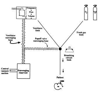
Figure 1. A diagram of the four limbs of the breathing system: (1) the breathing circuit limb, (2) the fresh gas supply limb, (3) the ventilator limb, and (4) the scavenging system limb.
The differential diagnosis of a low-pressure alarm condition must first be developed. In any mechanical ventilation system, there are four principal components: a) a source of gas; b) a conducting system (or breathing circuit); c) a pressure generator, i.e., a mechanical ventilator; and (d) a waste gas scavenging system. For the purpose of creating an algorithm, these components can be thought of as merging at a common point: the switchover point between mechanical and manual ventilation, as illustrated diagramatically in Figure 1. The scavenging system interfaces only with the ventilator limb and at the adjustable pressure-limiting (popoff) valve. In other words, the causes of low-pressure can be generally characterized as : a) inadequate fresh gas inflow; b) a breathing system leak or obstruction; c) a faulty or inappropriately set mechanical ventilator; or d) an excess removal of gas from the breathing system. Any useful algorithm must guide the anesthesiologist through these four limbs of the overall ventilation system, taking into account the common intersection point.
The Algorithm: Description of Logic
Initial Response to the Low-Pressure Alarm Condition
It is the anesthesiologist’s first priority to assure that the patient’s lungs are ventilated. In the algorithm to be developed below, it is assumed that the anesthesiologist has available a back-up or default method of ventilation, specifically, a self-inflating resuscitation bag (e.g., Ambu bag) with a cylinder-supplied 100% oxygen source. Furthermore, it is assumed that the anesthesiologist knows the general characteristics of the low-pressure monitor, particularly its pressure sensing location within the breathing system and its alarm limit settings.
Scan the monitored variables
If an alarm is annunciated, the first step is to scan the patient variables as reflected by the available monitors, including the pulse oximeter, end-tidal CO2, and the pressure gauge or pressure trace. Upon visual and auditory confirmation of the alarm as the low-pressure alarm, one then proceeds to utilize the algorithm as shown in Figure 2.
On older machines that lack a “bag-ventilator” selector valve, the adjustable pressure-limiting (APL or “popoff”) valve should be closed during automatic mechanical ventilation.
Check for total or partial disconnections
One checks for total or apparent partial disconnections in the breathing circuit, beginning at the Y-piece and proceeding proximally, within a few seconds. Disconnections, which occur most commonly at the Y-piece, can be a cause of serious patient morbidity.7,18-21 Thus, all potential disconnection sites distal to the switchover point between mechanical and manual ventilation will be quickly examined, and the necessary reconnections made.
Switch to manual reservoir bag ventilation
If a total disconnection is not found, one switches over from mechanical to manual ventilation rather than wait for the next mechanical breath. Assuming there is no problem with the “manual/ventilator” selector switch, the change to manual ventilation excludes ventilator-related problems from consideration. This simplifies the immediate search for the cause by restricting it to either the breathing circuit or the fresh gas limb, which should be examined in that order.
Evaluation of the Breathing System Reservoir Bag using the Oxygen Flush Valve
A key feature of the low-pressure alarm algorithm revolves around the filling of the breathing system reservoir bag with 100% O2 using the O2 flush valve. There are three possible situations to consider: (1) If the reservoir bag fills with 100% O2, the pipeline-to-O2 flush valve system is intact, and one proceeds to evaluate the breathing circuit, followed by an evaluation of the fresh gas and ventilator limbs; (2) if the reservoir does not fill with O2, this suggests a problem with the fresh gas supply and/or the O2 flush valve pathways; and finally (3) if the reservoir bag fills but then collapses, this suggests a problem either with an active suction device in the breathing circuit, a misconnection, or a scavenging system malfunction. A specific pathway, as shown in Figure 2, is then followed in response to each of these three conditions.
Reservoir Bag Fills
Evaluation of the Breathing Circuit
One first considers the situation in which the reservoir bag fills properly, indicating that the pipeline-to- O2 flush valve system is intact. This requires evaluation of the breathing circuit as shown in Figure 2 below.
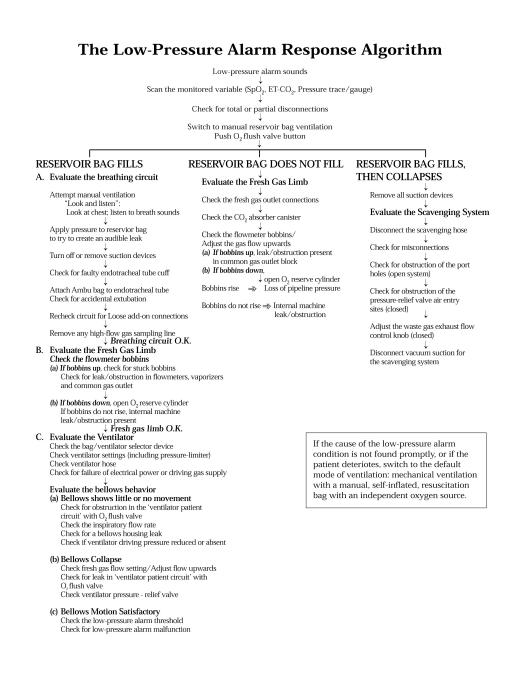
Figure 2. An algorithmic response to the breathing system low-pressure alarm condition. Note the use of O2 flush valve to determine which subalgorithm to pursue next.
Attempt manual ventilation
“Look and listen”: Look for chest wall motion, listen to breath sounds
With the bag now full, and with the adjustable pressure relief (“popoff”) valve partially closed, manual ventilation is attempted while the anesthesiologist looks at the patient’s chest and listens to the patient’s breath sounds. The circuit pressure gauge or the pressure trace monitor may indicate the inability to generate pressure within the circuit. If a capnograph and respirometer are available, they can be used to confirm tidal exhalation immediately after the “look and listen” maneuver.
If no breath sounds are present, if no chest wall motion occurs, and if no exhalation is evident from spirometer or capnograph, then the patient’s lungs are not being ventilated.
Apply pressure to manual reservoir bag to try to create an audible leak
With the creation of sufficient pressure within the reservoir bag, as high as 40 cm H2O, it may be possible to detect an audible leak resulting from a partial disconnection. With this done, one quickly proceeds to tighten the connections between the different components of the breathing circuit, beginning at the Y-piece area and proceeding proximally.
Turn off or remove suction devices
If no such leak or disconnection site is apparent, the next step is to remove any device that might be applying suction, such as a nasogastric tube, to see if this makes any difference. The reason for the removal of any present gastric tube is that it could have been mistakenly inserted into the trachea alongside the endotracheal tube and, with sufficient suction force, could be generating a low-pressure or even subatmospheric-pressure condition.22
If patient ventilation still does not occur with the use of the self-inflating resuscitation bag, the problem is with the location of the endotracheal tube or with a faulty cuff.
Check for faulty endotracheal tube cuff
If the endotracheal tube cuff is suspected to be torn, and ventilation is impaired such that replacement of the endotracheal tube is required, use of a tube exchanger should be considered in a patient with a difficult airway.
Attach Ambu bag to endotracheal tube/Check for accidental extubation
If the cuff is not deflated, one concludes that an accidental extubation has occurred. It is necessary then that the anesthesiologist remove the endotracheal tube, and provide manual ventilation using the reservoir bag with 100 % O2 until such time that the patient can be reintubated.
Recheck breathing circuit for loose connections
On the other hand, if manual ventilation with a reservoir bag results in satisfactory ventilation (good breath sounds and chest wall motion plus a positive CO2 trace), then the problem must reside elsewhere within the breathing circuit. Having previously excluded a visibly apparent disconnection, a cuff tear/ deflation, or a misplaced endotracheal tube as the cause of the circuit failure, one must now systematically examine the entire breathing circuit for a leak or an obstruction.
The anesthesiologist then checks methodically for loose connections at the following points: 1) endotracheal tube-to-adapter; 2) endotracheal tube adapter-to-breathing circuit; 3) sidestream sampling gas monitors (e.g., mass spectrometer, capnograph), condensor/ humidifier, pressure sensor, O2 analyzer, PEEP valve, or other “add-on” connections; 4) inspiratory and expiratory limb connections; and 5) reservoir bag mount-to-bag connection.
Remove high-flow gas analyzer sampling line
Both bronchoscopic suctioning, as well as high gas flow gas rates to a gas analyzer sampling line, could be withdrawing an excess volume of gas from the breathing circuit, and could cause a decrease in the circuit pressure. Any bronchoscope in the breathing system should be removed, and the high flow rate sidestream sampling gas analyzer should be disconnected from the system to determine if this makes any difference.
If manual ventilation with the circuit mounted reservoir bag results in chest wall motion, audible breath sounds, and a positive capnogram, and if the above methodical search fails to reveal any problem, one concludes that the breathing circuit is intact, and one’s attention should be directed next to the fresh gas limb.
Evaluation of the Fresh Gas Supply Limb
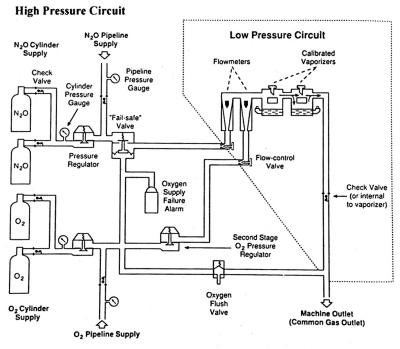
Figure 3. The fresh gas supply system Note that the flowmeter control valves divide the system into a high-pressure circuit and a low-pressure circuit. The check valve is not present on all machines. Reproduced with permission from J. Andrews, from ASA 1996 Annual Refresher Course Lectures, No. 722.
Because the manual reservoir bag filled upon opening the O2 flush valve, it follows there cannot be any leak or obstruction in the O2 flush valve pathway.
As shown in Figure 3, the fresh gas supply system is composed of a high-pressure system (which is located upstream of the O2 flowmeter control valve) and a low-pressure system (which is located downstream of the O2 flowmeter control valve). In the presence of a decrease in the O2 supply pressure within the high-pressure system upstream of the flowmeter control valve, the “fail-safe” valve shuts off or reduces the flow of N2O and other gases to the respective flowmeter control valve. However, the “fail-safe” valve does not respond to a reduced O2 supply pressure in the O2 low-pressure system, which is downstream of the O2 flowmeter control valve. For example, during the use of both N2O and O2, a leak or obstruction in the O2 flowmeter will not produce a corresponding decrease in the N2O gas flow, and a hypoxic mixture can be delivered to the machine common gas outlet and to the patient. In this case, the low-pressure alarm will fail to detect the problem. Detection of this problem requires a working O2 analyzer.
Check the Flowmeter bobbins
When the manual reservoir bag fills upon opening the O2 flush valve, one must check the bobbins to determine whether they move freely or are stuck, and if they are up or down.
(a) Check for stuck bobbins
If the flowmeter bobbins are up but do not change in position despite control knob adjustments, the bobbins are stuck in position. A stuck bobbin may or may not prevent gas flow downstream of the bobbins. Causes of stuck bobbins include dirt (especially from compressed air), non-vertical alignment of the flowmeters, and static electricity. If the bobbins do not respond to control knob adjustments, the anesthesia machine should be replaced, and the default mode of ventilation should be instituted.
(b) If the bobbins are up, check the flowmeters, vaporizers, and common gas outlet for a leak or obstruction
If the bobbins are up and move well, there may be an obstruction or leak distal to the bobbins, i.e., within the low-pressure system. If a major leak is present downstream of the flowmeters but upstream of the common gas outlet, the bobbins will be up, but there will be no flow or so little flow exiting the common gas outlet that the low-pressure alarm will be annunciated. Increasing the fresh gas flow may overcome such a leak, but not necessarily correct the underlying problem. In the presence of an obstruction downstream of the flowmeters, the back pressure is transmitted to the bobbins such that the gas within the flowmeters is compressed, and the bobbin floats at a lower position than before. As with a leak, there will be no flow or so little flow exiting the common gas outlet such that the low-pressure alarm is annunciated.
If no leak or obstruction is present in the flowmeters, one checks for a leak or obstruction involving the vaporizers (mounting, selector valve, etc.). If no leak or obstruction is apparent in the vaporizers, one then checks the remaining part of the distal part of the fresh gas supply limb by determining whether there is any gas flow emerging from the common gas outlet. If there is no flow exiting from this outlet, one concludes that there is a leak or obstruction somewhere in the fresh gas pathway downstream of the bobbins, but upstream of the common gas outlet. If such is the case, one resorts to the default mode of ventilation, and the anesthesia machine is replaced. Any situation requiring the default mode of ventilation should employ cylinder-supplied 100 % O2 with an independent flowmeter, or any other unimpaired ancillary O2 source.
In some anesthesia machines (Ohmeda), there is a common gas outlet check valve located downstream of the bobbins. The purpose of this check valve is to prevent retrograde gas flow from the breathing circuit into the machine. In anesthesia machines (North American Dräger) lacking such a check valve, during manual or controlled ventilation or with the use of the O2 flush valve, the positive pressure generated may be transmitted into the low-pressure system, and may make evident a leak within or distal to the flowmeters.
(c) If the bobbins are down, open the O2 reserve cylinder
If the bobbins stay down, an internal machine leak or obstruction is present.
If the bobbins are down, one opens the O2 reserve cylinder. If the bobbins stay down, there is an obstruction or leak proximal to the flowmeter control valve, i.e., within the high-pressure system. This means the default mode of ventilation must be employed, and the anesthesia machine replaced.
Finally, if no problem is evident within the breathing circuit or within the fresh gas supply limb, one proceeds next to the evaluation of the ventilator limb.
Evaluation of the Ventilator Limb
The subalgorithm for the ventilator limb presented here is applicable to a ventilator with an ascending bellows. While still manually ventilating the patient’s lungs, one needs to do the following:
Check bag-ventilator selector valve
In the case of a bag-ventilator selector valve that automatically excludes the APL valve from the system during mechanical ventilation, the selector valve should be in the appropriate “ventilator” position and not in the “bag” position, which is intended for manual ventilation. In the latter case, a ventilator with a full bellows will exert pressure uselessly against a completely closed selector valve.
Check ventilator settings (including pressure limiter)
Check the settings for tidal volume, ventilatory rate, and with the use of a spirometer, check the delivered tidal volume and adjust the inspiratory flow rate. After making these adjustments, one switches from manual reservoir bag ventilation to mechanical ventilation to determine whether this makes a difference. Check that the pressure limiter setting has not been set below the low-pressure alarm threshold; should this be the case, the generated breathing system pressure will be insufficient to satisfy the pressure monitor threshold criteria, and the low-pressure alarm will be annunciated.
Check ventilator hose
Check for a ventilator hose leak, obstruction, or disconnection (the ventilator hose is connected at one end to the ventilator and at the other to its point of attachment to the breathing system).
Check for failure of electrical power or driving gas supply
After the ventilator is switched on, failure to cycle means that the ventilator electrical power has failed or been turned off, or that the driving gas supply to the ventilator has been disconnected, shut off, or is at too low a pressure. In this case, assuming that the ventilator rate setting has not been set to zero, the ventilator will need to be replaced.
Evaluate the bellows behavior
One now considers three possibilities: (a) the bellows show little or no movement with ventilator cycling; (b) the bellows is collapsed; and (c) the bellows cyclic motion is satisfactory.
(a) Bellows shows little or no movement
If the ventilator cycles but the bellows shows little or no movement, either a significant obstruction is present in the pathway between the bellows and the breathing circuit, a reduced supply or excess venting of the driving gas has occurred, or there is a ventilator canister leak.
Check for obstruction in the ‘ventilator patient circuit’ with the O2 flush valve
The O2 supply flush valve should be opened first to evaluate the ‘ventilator patient circuit’ which extends from the bellows opening to its connecting point with the patient breathing circuit. If, after opening the O2 supply flush valve, there is no bellows movement, the problem is an obstruction in the ventilator patient circuit (the selector switch in “bag” position is one type of obstruction). If an obstruction is the problem, manual bag ventilation will have to be performed while the ventilator is being replaced. However, if the bellows does expand to some extent, an obstruction is most likely not the problem.
Check the inspiratory flow rate
If the inspiratory flow rate is very low or zero, it should be adjusted upwards on the ventilator. If bellows compression resumes, the problem was with a very low or zero setting for the inspiratory flow rate.
Check for a bellows housing leak/Check if ventilator driving gas pressure is reduced or absent
If there is still little or no bellows movement, one concludes that there is an inadequate ventilator driving gas pressure being generated with which to compress the bellows. One looks for an evident break in the bellows housing, and listens for a leak around the bellows housing. If such a bellows housing defect is found, one replaces the bellows housing. Otherwise, one must consider that the cause is a reduction in the driving gas supply pressure (which should cause the reduced driving gas supply pressure alarm to be annunciated) or there is an excess venting of the driving gas during the compression cycle (which may produce an evident leak). For these two cases, the ventilator and perhaps the anesthesia machine should be replaced.
(b) Bellows collapse
Check fresh gas flow setting
If the ventilator cycles properly but does not reach its usual end-expiratory stop, one should suspect that the setting for the fresh gas flow may be too low or even zero. The fresh gas flow should be increased to an acceptable level. When this is done, if the bellows becomes fully compressible in a cyclical manner, the problem was the very low or zero setting for the fresh gas flow, and most likely reflects a small internal leak that was overcome by the increase in fresh gas flow. If the bellows still collapses despite the increase in the fresh gas flow, the problem may be a major leak somewhere in the ventilator patient circuit.
Check for leak in ‘ventilator patient circuit’ with O2 flush valve
If an ascending bellows collapses, the most likely cause is a leak in the ‘ventilator patient circuit’, i.e., in the pathway extending from the opening of the bellows to the breathing circuit, and including the pathway from the bellows to the ventilator pressure-relief valve. One method of quickly checking the integrity of the pathway from the bellows to the breathing circuit is to open the O2 flush valve with the “bag-ventilator” selector valve in the ventilator position. If the bellows fully expands upon opening the O2 flush valve, this may suggest a significant leak that was overcome by the high O2 flow rate. For total leaks, the bellows will not rise, but presumably a loud hissing noise would be present.
Check the ventilator pressure-relief valve
One possible site for the leak is the ventilator pressure-relief valve. Normally, during the inspiratory phase of a mechanical ventilation cycle, the ventilator pressure-relief valve is held closed by the pressure of the driving gas. Closure of this valve during inspiration prevents breathing system gas from entering the scavenging system and directs all breathing system gas to the patient circuit. At end-expiration, the valve opens and allows waste gas to the enter the scavenging system and, if a scavenging reservoir bag is present, to cause distention of the bag.
If the ventilator relief valve is incompetent, gas intended for the breathing circuit during inspiration passes instead more easily to the lower-resistance scavenging system. Hence, there is no pressure increase in the breathing circuit and the low-pressure alarm is annunciated. In essence, the faulty ventilator pressure-relief valve causes a continuous leak, such that the bellows progressively deflates in the same manner as described above for zero fresh gas flow. Indeed, small leaks owing to a faulty ventilator pressure-relief valve can be compensated in part by increases in the fresh gas flow; on the other hand, they can be accelerated by a higher vacuum flow applied via the scavenging system. Causes of an incompetent ventilator pressure-relief valve include ventilator valve rupture (NAD),23 flapper valve malfunction (Ohio),24 and a disconnected pilot line.25,26 The detection of a faulty ventilator pressure-relief valve may be accomplished by disconnecting the ventilator scavenging hose, and listening for a leak during inspiration. In a closed scavenging system, another method by which to detect a faulty ventilator pressure-relief valve is to check for paradoxical distention of the scavenging system reservoir bag during inspiration.
If neither of these two methods reveals the presence of a leak in the ventilator pressure-relief valve, the default mode of ventilation is employed and the ventilator is replaced.
In the presence of a collapsed bellows, if increasing the fresh gas flow and inspiratory flow rate settings fails to correct the low-pressure alarm condition, and if no immediately correctable leak or disconnection is evident in the ventilator, the patient’s lungs should be ventilated with the manual reservoir bag and the ventilator should be replaced.
(c) Bellows motion satisfactory
Check the low-pressure alarm threshold
If the ventilator appears to be functioning properly, one must consider either a malfunctioning or an improperly set pressure-alarm device (a false-positive condition). If it is possible to adjust the low-pressure alarm threshold, one should do so. If no such adjustment is possible, one concludes that the low-pressure alarm is malfunctioning. An alarm that does not work is more dangerous than no alarm at all,27 and it should be repaired immediately.
Because it is possible for a problem in the fresh gas supply system to also produce a low-pressure alarm condition in which the manual reservoir bag does not fill upon opening the O2 flush valve, one proceeds next to this component of the breathing system.
Reservoir Bag Does Not Fill
One now considers the situation in which the reservoir bag does not fill when the O2 flush valve is opened. There are four main possible causes: (1) a loss or reduction of pipeline pressure; (2) an internal machine leak or obstruction; (3) a fresh gas flow disconnection or obstruction between the machine common gas outlet and the breathing system; and (4) a leak or obstruction in the CO2 absorber.
Check the fresh gas outlet hose and connections
The subalgorithm for the fresh gas limb begins with a visual inspection of the two fresh gas outlet connections (one connected to the anesthesia machine, the other to the breathing circuit). If no total fresh gas flow disconnection or hose occlusion is apparent, the actual fresh gas outlet connections should be physically reattached to avoid missing a partial disconnection, and the tubing between them should be checked for evidence of obstruction. Detection of a disconnect at the common gas outlet may be facilitated by the reduction in the value given by the oxygen analyzer.7
Check the CO2 absorber canister
An unlocked CO2 canister, or incomplete sealing of the CO2 canister housing (due to granules at the top of canister), can be the source of a significant gas leak and can cause failure of the reservoir bag to fill upon opening the O2 flush valve. If the CO2 canister is loose, it should be locked down tightly.
Check the flowmeter bobbins/Adjust the gas flow upwards
The flowmeter bobbins should be checked next to see if they are floating. If low flows are being used, the respective gas flow control knobs should be turned to higher flow settings.
If the bobbins are up, check for leak or obstruction in the common gas outlet block
If the bobbins are up, this suggests there is a leak or an obstruction in the common gas outlet block, i.e., distal to or at the junction between the O2 flush valve pathway (causing the reservoir bag not to fill) and the distal part of the fresh gas limb (downstream of the bobbins). Failure of sufficient gas to pass beyond the point of the leak or obstruction and into the common gas outlet presumably produced the low-pressure alarm condition. In this instance, the default mode of ventilation should be instituted and the anesthesia machine replaced.
If the bobbins are down, open the O2 reserve cylinder
If the bobbins then rise, check for loss of pipeline pressure
If loss of the O2 pipeline pressure is the problem, the corresponding source pressure alarm will be annunciated and the flowmeter bobbin will be down. In this case, the problem is corrected by opening an O2 reserve cylinder, which should result in the bobbins returning to their normal position. This, of course, necessitates further evaluation of the piline system (pressure gauges, gas hoses, and wall supply).
If the bobbins do not rise, an internal machine obstruction is present
If the bobbins do not rise upon opening an O2 reserve cylinder, this suggests a two-fold obstruction or leak involving the junction of the O2 flush valve conduit (which prevented the reservoir bag from filling) and the O2 supply pathway leading to the oxygen flow control valves (which caused the triggering of the low-pressure alarm). In short, if the bobbins are still down despite opening the O2 cylinder, an internal machine obstruction or leak may be present (otherwise, restoration of pressure should have sufficed to correct the problem), or there is a specific O2 reserve cylinder problem (O2 tank empty, cylinder mounted backwards in yoke, obstructed cylinder flow outlet valve, etc.) Once again, the default mode of ventilation–a manual, self-inflating resuscitation bag attached to tubing connected to an O2 cylinder via an independent flowmeter must be used while the machine is being replaced, or while the O2 cylinder problem is being corrected.
Regardless of whether the leak or obstruction is in the oxygen supply pathway, the flowmeter conduit, or in the O2 flush valve conduit, the response in all cases is the same: switch to the default mode of ventilation and replace the anesthesia machine.
Reservoir Bag Fills, Then Collapses
With a passive scavenging system, there is no active vacuum suction being applied to the system. Consequently, there is no concern about low or negative-pressure problems in passive systems. It is only when an active disposal mechanism with a central vacuum system is being used that these concerns about negative pressure arise.
Hazards of Excessive Negative Pressure in Active Scavenging Systems
In an active scavenging system, it is possible for an excessive negative pressure to develop and to be applied to the breathing system.26,28
If the negative-pressure relief valves or port holes were to be obstructed, little or no ambient air would enter to relieve the excessive negative pressure, causing a pronounced subatmospheric condition in the scavenging system. Obstruction of the negative pressure-relief valves in a closed system can be caused by plastic bags,29 dust,30 tape,31 and other objects.32,33 Obstruction of the reservoir port holes in an open system has not been reported.
During spontaneous ventilation, for certain APL valves, the excessive negative pressure may cause a loss of gas from the breathing system to the scavenging system, thereby producing a low or subatmospheric pressure in the breathing system.33,34 During automatic mechanical ventilation, however, if the ventilator pressure-relief valve is functioning properly, it is possible for an excessive negative pressure within the scavenging system to cause adverse changes in the breathing circuit–either an increase or a decrease in the breathing circuit pressure, depending on the ventilator interface with the scavenging system. For example, with an older version of the North American Dräger scavenging system interface with a single negative-pressure relief valve, a subatmospheric pressure was produced in the breathing circuit by a plastic bag blocking the negative-pressure relief valve.29
In the case of contemporary Ohmeda and North American Dräger ventilators, the most common result of excessive negative pressure in the scavenging system is to draw the ventilator relief valve to its seat, such that the excess waste gas cannot be released during exhalation; this in turn causes an increase in the breathing system pressure and puts the patient at risk for pulmonary barotrauma.32,35 In general, with diaphragm-type ventilator relief valves, unrelieved excess negative pressure in the scavenging system above generally causes the valve to be closed during exhalation, causing a high pressure situation rather than a low pressure alarm condition.31,33-35
If an active disposal system is used, a means must exist to limit the subatmospheric pressure. If a scavenging system reservoir bag is present, it can be used to gauge the rate of flow into the gas disposal system. If the reservoir bag is collapsed, the vacuum flow rate is excessive and should be decreased. Conversely, if the bag is markedly distended, the applied vacuum flow rate is too low relative to the waste anesthetic gas flow rate, and the vacuum flow rate should be increased. Problems arise when there is an absent or a malfunctioning control valve in the scavenging interface assembly. In this instance, the full vacuum flow rate will be applied directly to the ventilator pressure-relief valve, resulting in the same consequences as discussed above for the North American Dräger and Ohmeda ventilators.
Evaluation of the Waste Gas Scavenging System
In some scavenging systems (North American Dräger and Ohmeda), wall suction is usually applied downstream of the APL (“popoff”) valve, downstream of the ventilator pressure-relief valve, and at an air intake valve. If the circuit reservoir bag fills on using the O2 flush valve, but then collapses immediately, this situation should immediately suggest a vacuum source either within the breathing circuit, a misconnection, or less likely, excessive negative pressure within the scavenging system. Under these conditions, one would expect both the low-pressure alarm and the subatmospheric alarm (<-10 cm H2O) to be annunciated.
Remove all suction devices
One must discontinue the suction associated with any gastric tube, bronchoscope, or high-flow sidestream sampling gas analyzer, or remove these devices altogether. Gas sampling rates of sidestream sampling gas analyzers can range between 50 ml/min and 800 ml/min and, in the presence of low fresh-gas flow rates, could produce a low or even negative pressure in the breathing circuit.36 One should also consider the situation where the cause originates outside the breathing system, for example, when a surgeon places an active suction device in a bronchus.
An excessive negative pressure in the scavenging system of a modern anesthesia gas delivery system, such as those employed in Ohmeda and North American Dräger machines, by itself is unlikely to produce a low-pressure or subatmospheric condition. Rather, for the excess negative pressure to be transmitted to the breathing circuit, there must be a double-fault condition: a defective or stuck ventilator pressure-relief valve, plus excess negative pressure in the scavenging system. If the ventilator pressure-relief valve has a large defect, or if it is stuck such that it remains continuously open during inspiration and expiration, it will facilitate the transmission of the negative pressure within the scavenging system to the breathing circuit and produce a subatmospheric pressure condition.
Assuming suction devices have been eliminated from the breathing circuit, and if all other components of the breathing systems are intact, one examines the scavenging system as a potential source of the low-pressure alarm condition. In doing so, there are three main causes to consider: a blockage of the air intake valves, an absent or malfunctioning vacuum flow control valve at the scavenging interface, or excessive central vacuum suction pressure.
Disconnect the scavenging hose
For either a closed or an open reservoir, the first maneuver to perform is disconnection of the scavenging hose between the ventilator and the scavenging reservoir. This diagnostic maneuver, which takes priority over all others, takes only seconds to perform. This maneuver will cause all gases vented via the ventilator pressure-relief valve to be released into the operating room. If the low-pressure alarm is silenced as a consequence, the cause lies within the scavenging system.
Check for misconnections
If disconnection of the ventilator scavenging hose fails to relieve the low-pressure problem, and the manual circuit reservoir bag still collapses, suspect circuit failure in the form of a misconnection where the full vacuum flow rate is applied directly to the breathing system.
Check for obstruction of the port-holes (open system)
Check for obstruction of the pressure-relief valve air entry sites (closed system)
If removal of the ventilator scavenging hose relieves the negative-pressure problem, the problem is within the scavenging system. Indeed, it may be either an obstruction of the port holes in the scavenging reservoir collection system, or possibly an excessive central negative vacuum pressure being applied to the scavenging system. One should quickly look around the air entry sites and remove any possible obstruction (e.g., plastic wrapped around the air entry sites of the negative-pressure relief valves or the open system port holes).
Adjust the waste gas exhaust flow control knob (closed system)
If no obstruction is evident, one then adjusts the control knob that regulates the waste gas exhaust flow. If it is possible to relieve the problem by adjusting the knob, one concludes the problem was too high a setting for the waste gas removal exhaust flow relative to the capability of the air intake valves. This may suggest a partial obstruction of air intake valve(s). It should be noted that an internal blockage of the air intake valves (due to dust or lint) may be more difficult to detect promptly, and a trained anesthesia machine service person should be called.
Disconnect the vacuum suction from the scavenging system
If adjustment of the knob for the waste gas exhaust flow does not provide relief, and if no obstruction of the air entry sites at the port holes (open) or negative-pressure relief valves (closed) is evident, one concludes that there is a defective vacuum flow control valve in the scavenging interface, then one disconnects the vacuum suction from the scavenging system.
Default mode of ventilation
Because it is possible for even the default mode of ventilation to be ineffective in the case of an inadvertent extubation, esophageal intubation, or cuff leak, such that the patient will require mask ventilation and possible tracheal reintubation, it is critical to demonstrate at an early stage of the fresh gas limb subalgorithm algorithm that the patient can indeed be adequately ventilated using the default mode of ventilation. Clearly, it is mandatory that a manual, self-inflating, resuscitation bag with an independent source of oxygen be readily available in every operating room program for this purpose. Ideally, once adequacy of the default mode of ventilation has been established, this default method of ventilation should be continued while the cause of the low-pressure alarm condition is being investigated.
Although the declining O2 saturation is a late indicator of a breathing system malfunction, it is the final common pathway toward an adverse outcome. Hence, if the pulse oximeter indicates significant desaturation, or if the patient deteriorates at any time during the performance of the algorithm, the anesthesiologist must switch immediately to the default mode of manual resuscitation bag ventilation with 100% O2. If the underlying problem cannot be diagnosed by the algorithm within one minute while using the pulse oximeter as the guide, it is recommended that the default mode of ventilation be used instead.37
Nature of the Algorithm: Faults and Non-Uniqueness
The complete algorithm has been developed so that visual maneuvers can be performed initially as a scanning mechanism, which are then followed by the more detailed hands-on testing of the actual physical components, within each of the four limbs. In terms of the time required, the early key evaluative steps in the breathing circuit and fresh gas supply limbs should be performed quickly, indeed, within one minute.
The four-limbed algorithm is structured principally on a single-fault basis, although it accommodates rare double-fault conditions. It presumes that the cause of the low-pressure alarm condition can be localized to one of the four limbs, identified, and ultimately corrected. In the case of multiple, simultaneously occurring faults, the algorithm may be rendered less effective as a diagnostic aid. Nonetheless, a careful systematic check-out of each limb as previously described, focusing on one problem at a time, should detect the multiple errors even under these unusual circumstances.
During use of the algorithm, the alternative or default mode of manual resuscitation bag ventilation with 100 % O2 should be instituted immediately if the severity of the patient’s condition precludes further diagnostic evaluation. As before, the prescribed default mode of ventilation with a manual resuscitation bag is employed if the algorithm fails to reveal the underlying problem.
It should be pointed out that, in view of the variety and complexity of modern anesthesia equipment, no single algorithm can hope to cover all possible complications. However, it is worthwhile to formulate a general response plan to the low-pressure alarm condition. This response algorithm can then be modified to take into account the specific characteristics of the anesthesia breathing system in use. In this respect, the proposed algorithm is not unique. Nonetheless, the author believes that it serves as a valuable heuristic aid for the development of troubleshooting skills with an anesthesia machine during automatic mechanical ventilation.
Acknowledgments
This article is adapted from the author’s chapter in Progress in Anesthesiology, 1997, Vol. XI, Chapter 11, where the subcomponent flow-logic diagrams are presented in detail. Material from the article is used with the permission of the Dannemiller Memorial Educational Foundation in San Antonio, Texas. In preparing this article, the author would like to acknowledge the critical comments and suggestions made by several individuals, including Dr. James B. Eisenkraft, Dr. Michael Olimpio, Dr. J. Jeff Andrews, Dr. Robert Weller, Dr. Ralph A. Epstein, Mr. Daniel Doran, Mr. Jeff Kellywood, Mr. Paul Hill of Ohmeda, and Mr. Ken Horsefield of North American Dräger.
Dr. Raphael is Associate Professor of Clinical Anesthesiology, Department of Anesthesia, University of Medicine and Dentistry of New Jersey/Robert Wood Johnson Medical School, New Brunswick, NJ
References
1. “Standards of the American Society of Anesthesiologists”, 1996 Directory of Members, 60th Edit., 393-395.
2. Eichhorn JH, Cooper JB, Cullen DJ, Maier WR, Philip JH, Seeman RG. Standards for patient monitoring during anesthesia at Harvard Medical School; JAMA 256:1017-1020.
3. Eichhorn JH. Prevention of intraoperative anesthesia accidents and related injury through safety monitoring. Anesthesiology 1989; 70:572-577.
4. North American Dräger Narkomed 2A Anesthesia System Instruction Manual, Telford, Pennsylvania; 1987.
5. Ohmeda 7000, 7800, and 7900 Ventilator Product Descriptions, Ohmeda Inc., Madison, WI; 1986.
6. Lawrence JC. Breathing system gas pressure monitoring and venting, ventilator monitors and alarms. Anaesth Intens Care 1988; 16:38-40.
7. Schreiber P. Safety guidelines for anesthesia systems. Boston: Merchants Press, 1985, 44-45.
8. McEwen JA, Small CF, Saunders BA, Jenkins LC. Hazards associated with the use of disconnect monitors. Anesthesiology 1980;53:S391.
9. Reynolds AC. Disconnect alarm failure. Anesthesiology 1983;58:488.
10. Picard UM, Hancock DE, Pinchak AC. Pressure transients in anesthesia ventilators-failure of disconnect alarm system. Anesthesiology 1987; 67:A189.
11. Murphy PJ, Rabey PG. The Humphrey ADE breathing system and ventilator alarms. Anaesthesia 1991; 46: 1000 (L).
12. Slee TE and Pavlin EG. Failure of low pressure alarm associated with the use of a humidifier. Anesthesiology 1988; 69:791-793.
13. Milligan KA. Disablement of a ventilator disconnect alarm by a heat and moisture exchanger. Anaesthesia 1992; 47:279.
14. Ghanooni S, Wilks DH, Finestone SC. A case report of an unusual disconnection. Anesth Analg 1983; 62:696-7.
15. Mazza N, Wald A: Failure of battery-operated alarms. Anesthesiology 53:246-248, 1980.
16. Raphael DT, Weller RS, Doran DJ. A response algorithm for the low-pressure alarm condition. Anesth Analg 1988:67;876-883.
17. Raphael DT. An algorithmic response for the breathing system low-pressure alarm condition. Progress in Anesthesiology 1997, Vol. XI, Ch.11; 219-243.
18. Cooper JB, Newbower RS, Long DC, McPeek M. Preventable anesthesia mishaps: a study of human factors. Anesthesiology 1978; 49:399-406.
19. Cooper JB, Couvillon LA, eds. Boston: Arthur D. Little. Accidental Breathing Systems Disconnections Report prepared by the Center for Devices and Radiological Health, U.S. Department of Health and Human Services Publication FDA 86-4205, U.S. Government Printing Office, Washington, D.C.
20. Craig J. Wilson ME. A survey of anaesthetic misadventures. Anaesthesia 1981; 36:933-6.
21. Abramson NS, Wald KS, Grenvik ANA, Robinson D, Snider JV. Adverse occurrences in intensive care units. JAMA 1980; 244:1582-4.
22. Stirt JA, Lewenstein LN. Circle system failure induced by gastric suction. Anaesth Intens Care 1981; 9:161-2.
23. Sommer RM, Bhalla GS, Jackson JM, Cohen MI. Hypoventilation caused by ventilator valve rupture. Anesth Analg 1988: 67; 999-1001.
24. Khalil SN, Gholston TK, Binderman J, Antosh S. Flapper valve malfunction in an Ohio closed scavenging system. Anesth Analg 1987: 66; 1334-6.
25. Azar I, Eisenkraft JB: Waste anesthetic gas spillage and scavenging systems, Chapter 5. In: Anesthesia equipment: Principles and Applications, Ehrenwerth J, Eisenkraft JB (eds), St. Louis, Mosby – Year Book, 1993, pp 120-128.
26. Andrews JJ, @Inhaled anesthetic delivery systems?, Ch. 9 in Anesthesia, 4th Ed., Miller RM (Editor), Churchill Livingstone, New York, 209-216.
27. Pryn SJ, Cosse MM. Ventilator disconnexion alarm failures. Anaesthesia 1989; 44:978-981.
28. Ehrenwerth J, Eisenkraft JB. Anesthesia Equipment: Principles and Applications. St. Louis: Mosby-Year Book 1993: 120-128.
29. Patel KD, Dalal FY. A potential hazard of the Dräger scavenging interface system for wall suction. Anesth Analg. 1979; 58:327-8.
30. Seymour A. Possible hazards with an anaesthetic gas scavenging system. Anaesthesia 1987; 37: 1218.
31. Rendell-Baker L. Hazard of blocked scavenger valve. Can J Anaest 1982; 29: 182.
32. Sharrock NE, Leith DE. Potential pulmonary barotrauma when venting anesthetic gases to suction. Anesthesiology 1977; 46: 152-154.
33. Blackstock D, Forbes M. Analysis of an anaesthetic gas scavenging system hazard. Can J Anaesth 1989; 36 (2): 204-8.
34. Mor ZF, Stein ED, Orkin LR. A possible hazard in the use of a scavenging system. Anesthesiology 1977; 47: 302-303.
35. O’Connor DE, Daniels BW, Pfitzner J. Hazards of anaesthetic scavenging: case reports and brief review. Anaest Intens Care 1982; 10:15-19.
36. Mushlin PS, Mark JB, Elliott WR, Striz S, Goldman DB, Philip J. Inadvertent development of subatmospheric airway pressure during cardiopulmonary bypass. Anesthesiology 1989; 71:459-462.
37. Dorsch JA, Dorsch SE. Understanding Anesthesia Equipment, 2nd Edition. Baltimore: Williams and Wilkins, 1984: 301-304.